
| Home | Back to Parts Page | Previous Page | Next Page |
CHEST BUTTONS
I ordered
the
parts from Allied
Electronics, Inc
| Lighted Push button switch | KB 16CKW01 | NKK Switches of America | Stock Number 870-7021 | $5.75 each |
| Round white caps for lighted push button switch | AT486BB | NKK Switches of America | Stock Number 870-7028 | $0.90 each |
| Incandescent lamp, 12 VDC, 115mA, each7000Hrs | AT611-12V | NKK Switches of America | Stock Number 870-7018 | $1.68 each |
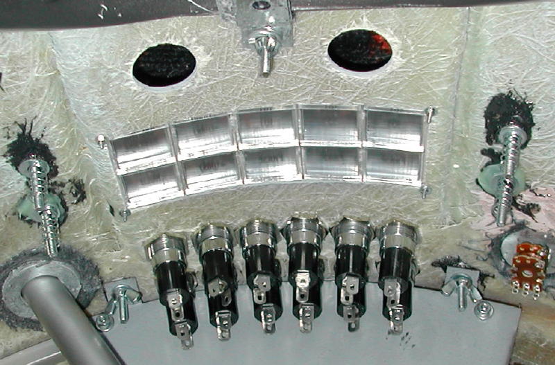
I created the interior bezel out of a piece of steel that I found in a hardware store. In order to position the "real" buttons in the center of each "external" button, I used the external bezel as a stencil. Using a ruler to draw diagonal lines, I found the true center of each rectangular external button. At this point, I drilled a hole. I wore out three expensive drill bits drilling these ten holes. Because of this, the interior bezel was a very expensive part to produce.
Once the holes were drilled, I bend the interior bezel to the correct curve. This was achieved by hammering.
The interior bezel is mounted on four bolts that are attached to the torso using the Reinbrecht method of gluing the bolts to the torso with epoxy.
In order for the "real" buttons to function, they must just touch the back of the "exterior" buttons. In order to achieve the correct contact pressure, I placed a spring over the bolts that hold the interior bezel in place. This spring pushes the bezel away from the exterior buttons and allows me to precisely position the interior bezel so that the "real" buttons can be properly depressed and released by the external buttons.

Wiring the Switches
On the back of each switch, there are five little terminals. Naturally, the switches to not come with any instructions explaining the function of these terminals. With a little trial and error and much help from Mike Joyce, I was able to figure out a way to wire the switches so that they functioned according to my plan.
Here is a diagram of the back of the switch.
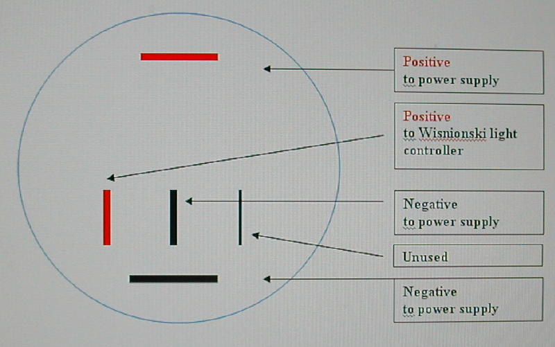
When wiring the switch, it is best to think of it as two separate components: a light bulb (horizontal terminals); and a standard switch (vertical terminals).
Light
bulb
(horizontal terminals)
The wires connected to the top
horizontal
terminal (marked "Positive to power supply") on every switch are wired
in parallel together to form a single positive wire that connects to
the
positive terminal block at the back of the robot's torso. I ran this
cable
through one of the toggle switches in the programming panel so that I
can
turn off all the lights in the chest buttons if I so choose. Even if
the
lights are all switched off, the switches still function and control
the
Wisnionski light controller.
The wires connected to the lower horizontal terminals on every switch (marked "Negative to power supply) are wired in parallel together to form a single wire that connects to the negative terminal block in the back of the robot's torso.
Switch
(vertical
terminals)
Each of the left most positive
vertical
terminals is wired to a corresponding five-pin connector that snaps
onto
the Wisnionski light controller.
The wires connected to the middle vertical terminals on every switch (marked "Negative to power supply) are twisted together to form a single wire that connects to the negative terminal block in the back of the robot's torso.
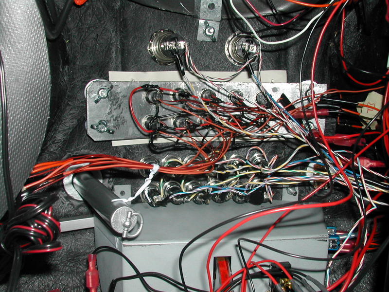
Here is a photograph of the mess of wires connected to the back of the switches. The Wisnionski light controller requires a lot of extra wiring that would not normally exist in a robot that used standard flasher bulbs instead of a microprocessor. It looks deceptively chaotic, but the wiring is orderly and easy to follow.
When everything is hooked up, as shown, each chest buttons activates the following light modes.
From left to right (looking at the buttons, facing the robot), top row
Button 1 = Switch 1 = Alternate
Scan
Effect
Button 2 = Switch 2 = Chase Light
Effect
Button 3 = Switch 3 = Scanner
Button 4 = Switch 4 = Overall
Speed
of Lamp cycles, Controls all the modes
Button 5 = Switch 5 = Power Down/
up effect (Flip it, and the lights slowly blink out, release it, and
they
slowly come back to normal cycle)